Page 1 of 1
Suspension Design

Posted:
Wed Feb 17, 2010 10:09 amby Ricey88
I am Using the software Susprog3d to Calculate new suspension pickup points.
Does anyone know how to enter the rear uprights pickup points for an upright that has one top
point, two lower points AND a toe arm point. The two lower points are what I have been
unable to work out how to enter them, the X and Y are the same but I have two Z coordinates
to enter and only one place to put them.
Any help or suggestions, or ideas on other cheap software that will help, would be appreciated
Inboard Vs Outboard springs and dampers
Re: unsprung weight.
Is it unsprung weight or unsprung mass that affects the compliance of the tyers to the road.
In moving suspension would it be about the unsprung moving mass, and that would include
the mass of the rod and rocker, therfore greater unsprung mass on inboard suspension?
a bad thing???
Ricey
Suspension Design
Posted:
Wed Feb 17, 2010 10:39 amby Toyzda
Hey Ricey,
Outboard suspension has the mass of the spring and shock (a percentage of it any way depending where your mounting points are) which, in any design, is far heavier than a push rod. The rocker is on a pivot which is sprung. Pushrod suspension is the only way to go, especially since you have CAD software.
Two lower points AND a toe arm point? I guess you are using two separate lower arms rather than an A arm? If so, to enter the Z axis you would have to work out the pivot centre of the two lower arms. This would be half way between the two if you had a parrarelogram. It would be a far superior design utilising an A arm. You could utilise one of the points on the upright only. Try entering one of the points, then the other and see which gives you the desired geomtry.
What car are you building? What upright you using with two lower points?
M
Suspension Design
Posted:
Wed Feb 17, 2010 10:49 amby Ricey88
Harrop / monaro nations cup rear uprights
Suspension Design
Posted:
Wed Feb 17, 2010 12:30 pmby Toyzda
Can you attach a photo of the hubs, showing the lower mounts?
Suspension Design
Posted:
Thu Feb 18, 2010 9:26 amby profi
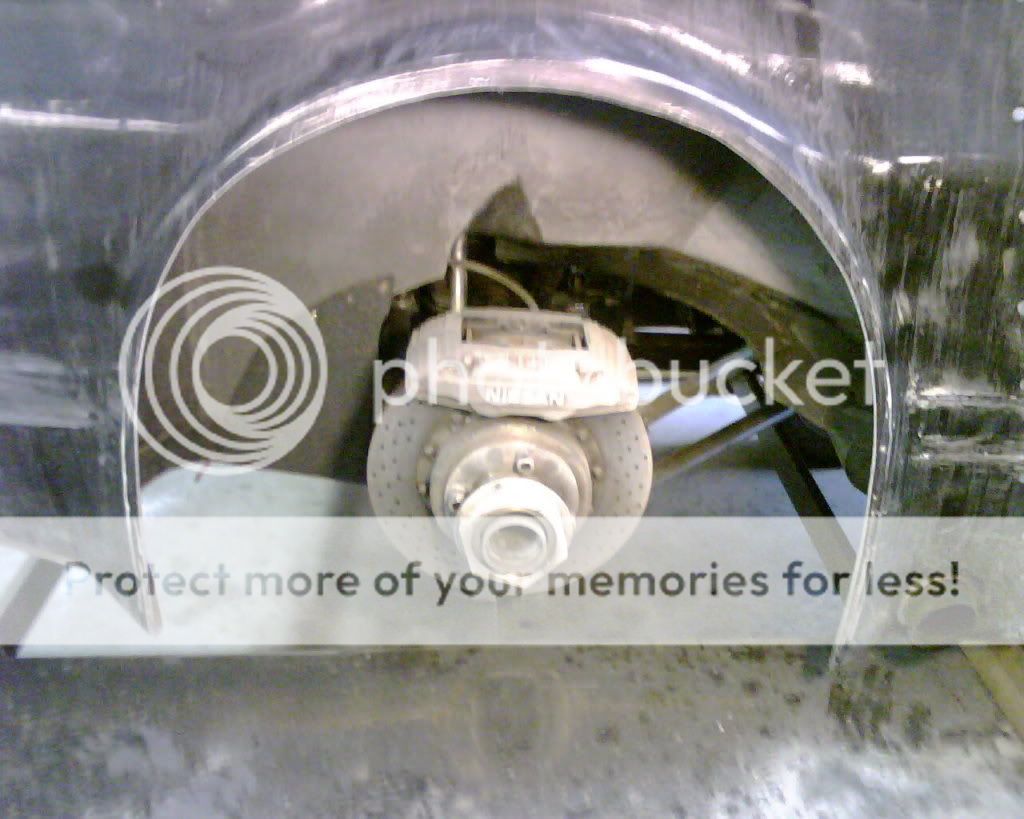
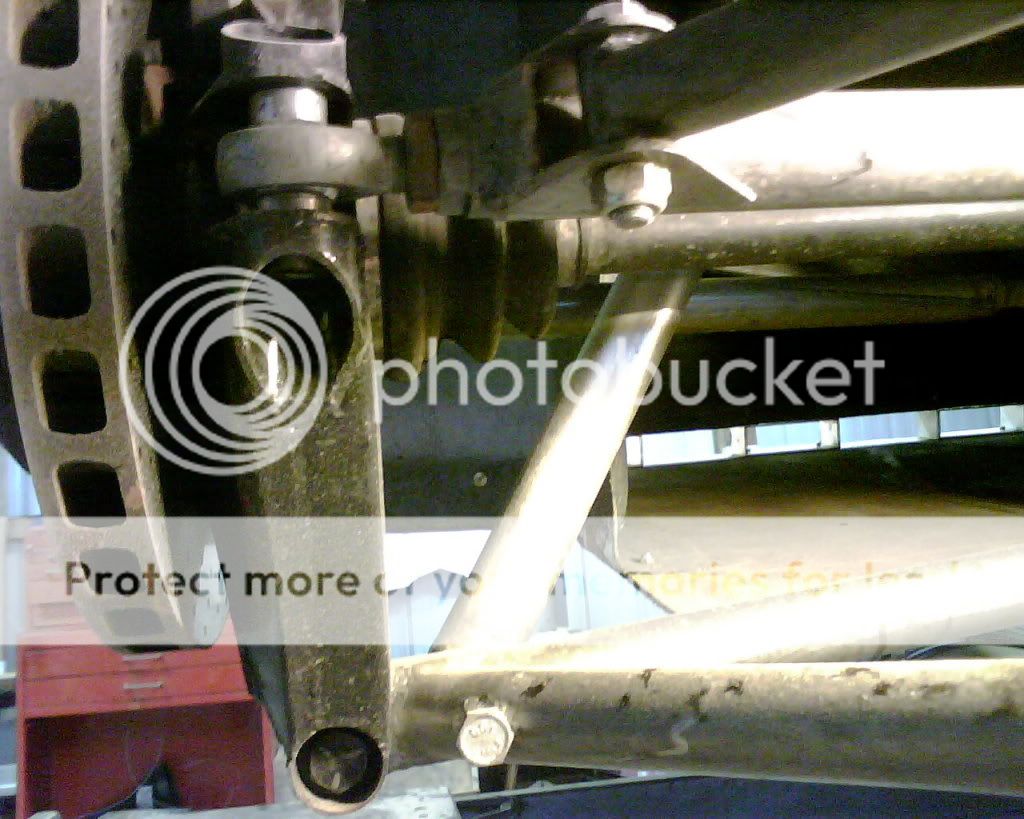
Riceys upright.
Suspension Design
Posted:
Thu Feb 18, 2010 1:53 pmby Toyzda
It looks like the CNC'ed aluminium mount is used to mount the spring/ shock? This looks like it is designed to suit the "original pickup points" rule for production cars. You could still use this quite effectively. I am not sure how your CAD software calculates geomtry, but the bottom mount and tie rod mount are in a different plane to the top mount which could cause issues in the software? I don't know though, it will probably work it out no problems.
Suspension Design
Posted:
Thu Feb 18, 2010 2:05 pmby Ricey88
On the N C Monaro, that AL bracket is a pickup point for a full length arm to chassis pickup point,
The arm had the shocker/spring mount on it.
Suspension Design
Posted:
Thu Feb 18, 2010 2:34 pmby Toyzda
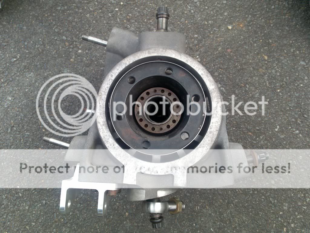
I wouldn't use the lower spherical peg at all. I would use the aluminium bracket, top spherical peg and the tie rod spherical peg. This should give 3 good points for your CAD.
I will take some photo's of my uprights and rear suspension on the car. The pickup points are similar to yours, just upside down.
Suspension Design
Posted:
Fri Feb 19, 2010 11:01 amby Toyzda
Photo's of my rear upright. I have also added these and more on "new sports sedans" thread.
rear upright top

rear upright back
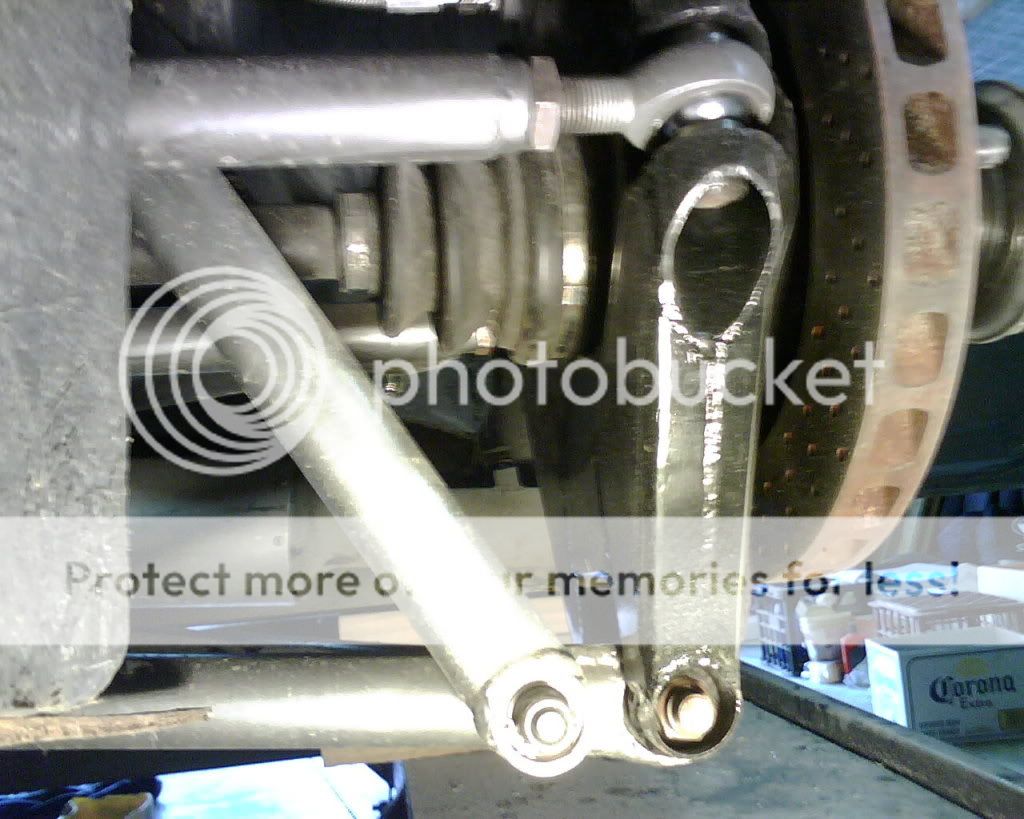
rear upright inside
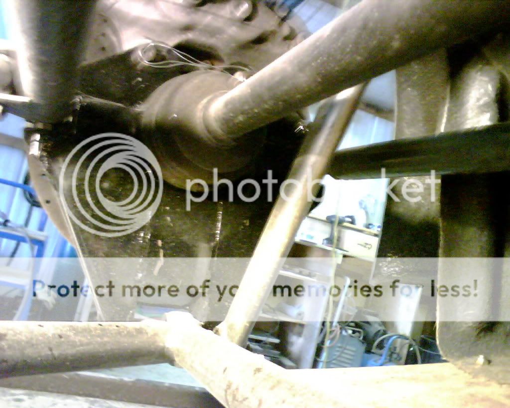
rear upright front
rear right corner