1984 Ford Laser KB - Rover 3.5L V8
42 posts
• Page 2 of 5 • 1, 2, 3, 4, 5
1984 Ford Laser KB - Rover 3.5L V8
![]() by jd yort » Fri Apr 27, 2012 8:06 pm
by jd yort » Fri Apr 27, 2012 8:06 pm
Great thread acco, keep the pics and the challenges of the build coming. Enjoying the read.
-
jd yort - Posts: 747
- Joined: Fri Jun 15, 2007 9:49 pm
- Location: Sydney
1984 Ford Laser KB - Rover 3.5L V8
![]() by accomotors » Mon May 07, 2012 7:06 pm
by accomotors » Mon May 07, 2012 7:06 pm
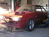
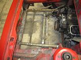
Been doing a little more work on the car lately, just an hour here and an hour there after work. Got other projects going concurrently so if progress here seems slow it doesn't mean I'm being lazy just productive in other areas :-).
While we are waiting to get a set of wheels so as to finalize the rear end location (Simmons B45 is what we are looking for if anyone has some they want to donate?!) we started on the front end. This has kind of been a topic we have skirted around because of the perceived difficulty in figuring something out. We toyed with the idea of the Torana front end as suggested, but the more we thought about it and the less we felt like making the thing fit, the more we liked the idea of using as much standard Laser stuff as we could. Being that we were able to fit the motor in between the de-facto rails meant the standard suspension retained much of it's factory strength left us thinking.
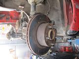
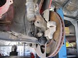
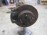
We thought we would begin by investigating the cheapest and easiest options first and work our way up from there. That meant we had to find a Commodore stub/hub to mount our donated VY brakes on. I got one from the wreckers off of a VT and took it home for trial fitment. Believe it or not a Commodore stub/hub assembly is pretty much a bolt-in conversion for a Ford Laser KB! The two macpherson strut mount bolts are only about 1/32 of an inch different (they fit if you use one Commodore bolt and one Laser bolt) and the ball joint fits but the Laser one is slightly smaller.
We couldn't believe it, what luck!! We put the brake and caliper on and tried fitting the stock Commodore wheels we have been using. No go. The wheel hits on the spring mount on the strut. We thought we might have to use Laser 'coil-over' strut conversion struts because of the decreased diameter but another mate came up with a good idea. Bolt the UPPER hole on the stub/hub to the LOWER hole on the Laser strut and make up a 3-hole plate on each side to join the lot together. So we trial fitted the stub/hub into the lower hole and put the wheel back on. Bingo!
Also put the XF Falcon rear brakes on the VL diff but more of that when we get it finished and get some photos.
While we are waiting to get a set of wheels so as to finalize the rear end location (Simmons B45 is what we are looking for if anyone has some they want to donate?!) we started on the front end. This has kind of been a topic we have skirted around because of the perceived difficulty in figuring something out. We toyed with the idea of the Torana front end as suggested, but the more we thought about it and the less we felt like making the thing fit, the more we liked the idea of using as much standard Laser stuff as we could. Being that we were able to fit the motor in between the de-facto rails meant the standard suspension retained much of it's factory strength left us thinking.
We thought we would begin by investigating the cheapest and easiest options first and work our way up from there. That meant we had to find a Commodore stub/hub to mount our donated VY brakes on. I got one from the wreckers off of a VT and took it home for trial fitment. Believe it or not a Commodore stub/hub assembly is pretty much a bolt-in conversion for a Ford Laser KB! The two macpherson strut mount bolts are only about 1/32 of an inch different (they fit if you use one Commodore bolt and one Laser bolt) and the ball joint fits but the Laser one is slightly smaller.
We couldn't believe it, what luck!! We put the brake and caliper on and tried fitting the stock Commodore wheels we have been using. No go. The wheel hits on the spring mount on the strut. We thought we might have to use Laser 'coil-over' strut conversion struts because of the decreased diameter but another mate came up with a good idea. Bolt the UPPER hole on the stub/hub to the LOWER hole on the Laser strut and make up a 3-hole plate on each side to join the lot together. So we trial fitted the stub/hub into the lower hole and put the wheel back on. Bingo!


Also put the XF Falcon rear brakes on the VL diff but more of that when we get it finished and get some photos.
-

accomotors - Posts: 36
- Joined: Sun Jun 13, 2010 8:56 pm
1984 Ford Laser KB - Rover 3.5L V8
![]() by Toyzda » Tue May 08, 2012 9:07 am
by Toyzda » Tue May 08, 2012 9:07 am
Are you kidding me!!! That front upright and strut need to be fastened in a way to stop camber change (like he original 2 bolts....). What happens when you put load on the upgright, like for instance putting the car back on the ground? What about your ride height change, never mind the safety issues? I do hope you will be modifying the strut to eliminate this issue?
I am glad and interested in the "budget" build you are doing here. It is a great idea and a showcase on the origins of SS building, but i am concerned about the safety and engineering priciples not being applied in these examples.
I am glad and interested in the "budget" build you are doing here. It is a great idea and a showcase on the origins of SS building, but i am concerned about the safety and engineering priciples not being applied in these examples.
-

Toyzda - Posts: 155
- Joined: Thu Feb 04, 2010 8:28 pm
1984 Ford Laser KB - Rover 3.5L V8
![]() by Htc Motorsport » Tue May 08, 2012 10:58 am
by Htc Motorsport » Tue May 08, 2012 10:58 am
What does it matter, LET HIM GET IT OUT THERE FIRST BEFORE YOU START BAGGING IT FOR CHRIST SAKE....its not your concern, get out and run what you brung. Its his melon in the thing. This is the reason no one gets into motor racing, its to bloody hard to deal with all the rules and regs and red tape as it is, without having to put up with peoples opinions that don't matter.
He will work that out once he's out there and start to rectify all the little things as he goes and besides he might like to drive a car with camber and ride height change. I say go for it.
There's been plenty of death traps in Sports Sedans that have been quick, fast, light weight and exciting over the years and the owners and drivers are all still here to talk about the good old days. Bring it on.
-

Htc Motorsport - Posts: 300
- Joined: Thu Nov 01, 2007 7:51 am
1984 Ford Laser KB - Rover 3.5L V8
![]() by accomotors » Tue May 08, 2012 6:56 pm
by accomotors » Tue May 08, 2012 6:56 pm
Mate, we aren't just leaving that one bolt in holding the lot together, it's still going to have the factory alignment and all the holes will be used. Have a read through dude, don't just look at the pictures.
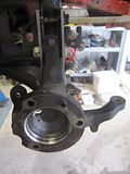
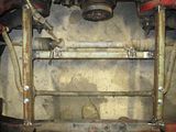
Went back to the wreckers yesterday and grabbed the other stub/hub. We figured we're going to sleeve the Commodore stub/hub down to the Laser ball joint size because using the Commodore ball joint in the Laser control arm won't work as they're fastened differently. Regarding the ride height as mentioned above, the modified axle centerline hangs at the same height as the unmodified Laser strut on the other side.
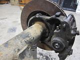
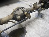
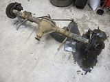
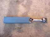
We got the rear end finished tonite. It is a VL housing and axles using an XF watts link assembly, LSD hemisphere and brakes. The Borg Warner 78 series diffs common to both these cars use a lot of common parts and this was part of the reason for choosing it. We had to modify the caliper mounting brackets (aluminium) because the plates on the ends of the axle tubes are different. We also had to modify the discs to slip over the Commodore axles and put XF Falcon bearings/seals on the VL axles because the seal (which doubles as a bearing preloader) is a different thickness to make up for the thicker caliper mount (as opposed to the drum brake backing plate). We are yet to put the LSD in as this setup is mostly for alignment purposes while we get the diff installed.
Went back to the wreckers yesterday and grabbed the other stub/hub. We figured we're going to sleeve the Commodore stub/hub down to the Laser ball joint size because using the Commodore ball joint in the Laser control arm won't work as they're fastened differently. Regarding the ride height as mentioned above, the modified axle centerline hangs at the same height as the unmodified Laser strut on the other side.


We got the rear end finished tonite. It is a VL housing and axles using an XF watts link assembly, LSD hemisphere and brakes. The Borg Warner 78 series diffs common to both these cars use a lot of common parts and this was part of the reason for choosing it. We had to modify the caliper mounting brackets (aluminium) because the plates on the ends of the axle tubes are different. We also had to modify the discs to slip over the Commodore axles and put XF Falcon bearings/seals on the VL axles because the seal (which doubles as a bearing preloader) is a different thickness to make up for the thicker caliper mount (as opposed to the drum brake backing plate). We are yet to put the LSD in as this setup is mostly for alignment purposes while we get the diff installed.
-
accomotors - Posts: 36
- Joined: Sun Jun 13, 2010 8:56 pm
1984 Ford Laser KB - Rover 3.5L V8
![]() by proey » Tue May 08, 2012 8:10 pm
by proey » Tue May 08, 2012 8:10 pm
Hi mate good to see an old school build up. One thing to be aware of with the commodore hubs is the stub alxe is not inline with the hub centre line. Its in front when on a commodore but with the way you have them mounted it will be behind which will make the steering very heavy. I know from experience!
-
proey - Posts: 43
- Joined: Fri Jun 12, 2009 8:42 pm

1984 Ford Laser KB - Rover 3.5L V8
![]() by accomotors » Tue May 08, 2012 8:20 pm
by accomotors » Tue May 08, 2012 8:20 pm
Hey proey, thanks for the support. We'll have to check that out.
-
accomotors - Posts: 36
- Joined: Sun Jun 13, 2010 8:56 pm
1984 Ford Laser KB - Rover 3.5L V8
![]() by accomotors » Sat Jun 16, 2012 6:09 pm
by accomotors » Sat Jun 16, 2012 6:09 pm
Finally got some more work done on the car today. Had a few things happening and also been finishing off getting my shed set up; it's not finished yet but at least I've got a bench and everything now.
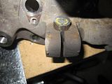
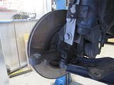
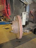
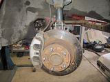
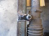
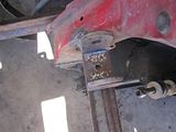
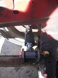
We have finally got the front strut/brake/stub setup in and it worked out great, just as we planned. The biggest hurdle we saw was getting the Laser ball joint into the Commodore stub as the Commodore is larger and therefore the bolt is unable to hold the Laser ball joint in. We thought of sleeving the ball joint out to the Commodore size but realized the relief built into the joint for the bolt to hold it in would be lost so we devised another solution. The Commodore stub would have the hole filled using a mild steel rod of the same diameter as the hole, then it would be offset drilled to the Laser size and use a Laser bolt to retain the whole lot.
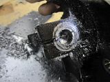
Worked a treat!
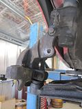
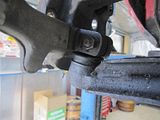
Next was the bracing for the upright. The plan remained the same as previously described, so we went about making up a couple brackets. The lower hole needs washers welded in for spacers for to make up the difference in width between the lower hole and that which passes through the Laser strut. The whole lot is aligned and looks a treat. Won't be going anywhere in a hurry that's for sure.
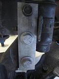
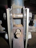
We put the brake and everything back on. We are going to get some longer bolts of the a slightly larger diameter and re-drill through all 3 holes. Otherwise it's good to go!
Next step is to weld in a couple box sections in the front to hold the steering rack and the sway bar.
We have finally got the front strut/brake/stub setup in and it worked out great, just as we planned. The biggest hurdle we saw was getting the Laser ball joint into the Commodore stub as the Commodore is larger and therefore the bolt is unable to hold the Laser ball joint in. We thought of sleeving the ball joint out to the Commodore size but realized the relief built into the joint for the bolt to hold it in would be lost so we devised another solution. The Commodore stub would have the hole filled using a mild steel rod of the same diameter as the hole, then it would be offset drilled to the Laser size and use a Laser bolt to retain the whole lot.


Worked a treat!
Next was the bracing for the upright. The plan remained the same as previously described, so we went about making up a couple brackets. The lower hole needs washers welded in for spacers for to make up the difference in width between the lower hole and that which passes through the Laser strut. The whole lot is aligned and looks a treat. Won't be going anywhere in a hurry that's for sure.


We put the brake and everything back on. We are going to get some longer bolts of the a slightly larger diameter and re-drill through all 3 holes. Otherwise it's good to go!


Next step is to weld in a couple box sections in the front to hold the steering rack and the sway bar.
-
accomotors - Posts: 36
- Joined: Sun Jun 13, 2010 8:56 pm
1984 Ford Laser KB - Rover 3.5L V8
![]() by accomotors » Sun Jun 24, 2012 12:15 pm
by accomotors » Sun Jun 24, 2012 12:15 pm
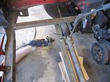
Back in the shed all day yesterday. The aim was to get the majority of the front end in and ready so that it is just the diff needing fitment for the car to roll. Got interrupted mid-way through the day to diagnose a mate's 4wd making a noise, turned out to be the intermediate driveshaft bearing so that ate up some time. Didn't finish until dark (much to the girlfriend's disgust!) but it was worth it.
First step was to finish off the mounts for the stub axles and struts. As explained in the previous post we we-drilled the existing holes to accept slightly larger bolts and then mirrored our efforts on the LH side of the car. Whole lots looks a treat now and is solid as a rock.
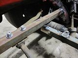
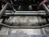
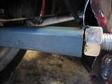
To start on the front end steering we had to weld in a couple of square tube pieces fore and aft that would act in a dual capacity. Firstly they would mount the sway bar and they would also hold another square tube which would mount the steering rack.
We then mounted some wheels on the car and lowered it onto the ground. We had to pull the springs off of the struts and re-install them as a shock only so the car would be low enough. The ride height was still too high as the tires hit on the guards before the car was fully down because of the additional track with the new brakes. The guards will be cut and flares added later. After we had the wheels on the ground we set them straight so as to align the steering rack.
We chocked the steering rack up and made a piece to go between the two new rails. We welded on some tabs to hold the rack and tacked the whole thing in place.
Then we put the sway bar into place using the factory holes supplied on the Laser control arms. We knew that the new rails would be roughly the right width to bolt the brackets on given the adjustment available on the sway bar rubber mounts so fitment was a simple 4 hole drilling procedure. We then put a few more solid welds on and pulled all the chocks out.
By the end of the day the welds were looking pretty sad as we had worked our little welder pretty hard. We'll have to go back and clean up some of what we did today but it is all in there and solid as anything. We're really looking forward to getting it rolling and with the front end done we turn our attention to the rear.
First step was to finish off the mounts for the stub axles and struts. As explained in the previous post we we-drilled the existing holes to accept slightly larger bolts and then mirrored our efforts on the LH side of the car. Whole lots looks a treat now and is solid as a rock.
To start on the front end steering we had to weld in a couple of square tube pieces fore and aft that would act in a dual capacity. Firstly they would mount the sway bar and they would also hold another square tube which would mount the steering rack.


We then mounted some wheels on the car and lowered it onto the ground. We had to pull the springs off of the struts and re-install them as a shock only so the car would be low enough. The ride height was still too high as the tires hit on the guards before the car was fully down because of the additional track with the new brakes. The guards will be cut and flares added later. After we had the wheels on the ground we set them straight so as to align the steering rack.


We chocked the steering rack up and made a piece to go between the two new rails. We welded on some tabs to hold the rack and tacked the whole thing in place.


Then we put the sway bar into place using the factory holes supplied on the Laser control arms. We knew that the new rails would be roughly the right width to bolt the brackets on given the adjustment available on the sway bar rubber mounts so fitment was a simple 4 hole drilling procedure. We then put a few more solid welds on and pulled all the chocks out.


By the end of the day the welds were looking pretty sad as we had worked our little welder pretty hard. We'll have to go back and clean up some of what we did today but it is all in there and solid as anything. We're really looking forward to getting it rolling and with the front end done we turn our attention to the rear.
-
accomotors - Posts: 36
- Joined: Sun Jun 13, 2010 8:56 pm
1984 Ford Laser KB - Rover 3.5L V8
![]() by accomotors » Sun Jul 22, 2012 11:09 am
by accomotors » Sun Jul 22, 2012 11:09 am
Well a slight change of plans from the last post. We might have jumped the gun a bit saying the front end was finished!
After we completed the last post we went back and dumped the car down low with the suspension as above. We have been working on about a 4" ride height taken from the rails on the bottom either side of where the motor sits now. We tried to get it down to about 2" from the ground so as to give us a couple of inches of suspension travel at the 4" ride height. When we tried to get it down that low it bottomed out on something. We took a look underneath and saw the angle of the suspension arms.
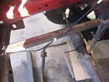
We were pretty silly assuming it would be OK but it's all about trial and error I reckon. After thinking about what we could do to fix it the only solution was to make up some new arms. A pretty daunting task for us as we had never done anything like that before, but after we looked at some angles and drew a couple things up we figured it could be done.
We got some box section, thread bar and bushes and decided to make up a single control arm with a radius rod for lateral location. We welded on a couple pickup points to the box section we had welded in previously. We made up a bush end with thread bar on it and made up some box section to adjust it in and out of. The box would also accept the ball joint we previously installed in the Commodore stub by cutting out and welding the mount from the old to new arm.
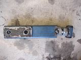
We put in a makeshift radius rod to test our concept but were unhappy with it for a few reasons, so we canned that and went with an A-arm. We would use the new control arm and fabricate another back in a similar direction but with the same bush and adjustment at the end of it. This would allow for camber and castor adjustment.
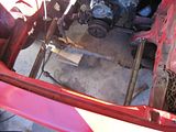
We had to relocate the rack and sway bar that we had mounted in before. Luckily we just had to flip them up to the top of the box sections and the alignment was OK again. Only other change was to cut some sections out of the body because they ran too close and would foul under normal suspenion movements.
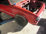
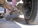
After we made up both sides of the suspension we put the car back down on the ground and we were good to go! It now sits about 1.5" off of the ground with no control arm angle issues. We cut out one of the guards for fun to see how much we had to take off. We removed the factory 'flare' section and stuck the guard back on, but it still needs a little more to get it to clear the guard. The inner guard/footwell also needs relieving to allow the full range of movement under full compression/lock.
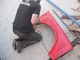
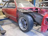
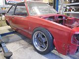
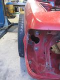
As you can see the tire sits outside the line of the guard but nearly in line with the factory width when the 'flare' part was still on there.
We don't have as many photos as the last few posts as with the shed getting more and more equipped we are able to do a few jobs at a time which doesn't leave me much time for taking photos of others hard at work!
After we completed the last post we went back and dumped the car down low with the suspension as above. We have been working on about a 4" ride height taken from the rails on the bottom either side of where the motor sits now. We tried to get it down to about 2" from the ground so as to give us a couple of inches of suspension travel at the 4" ride height. When we tried to get it down that low it bottomed out on something. We took a look underneath and saw the angle of the suspension arms.

We were pretty silly assuming it would be OK but it's all about trial and error I reckon. After thinking about what we could do to fix it the only solution was to make up some new arms. A pretty daunting task for us as we had never done anything like that before, but after we looked at some angles and drew a couple things up we figured it could be done.
We got some box section, thread bar and bushes and decided to make up a single control arm with a radius rod for lateral location. We welded on a couple pickup points to the box section we had welded in previously. We made up a bush end with thread bar on it and made up some box section to adjust it in and out of. The box would also accept the ball joint we previously installed in the Commodore stub by cutting out and welding the mount from the old to new arm.


We put in a makeshift radius rod to test our concept but were unhappy with it for a few reasons, so we canned that and went with an A-arm. We would use the new control arm and fabricate another back in a similar direction but with the same bush and adjustment at the end of it. This would allow for camber and castor adjustment.
We had to relocate the rack and sway bar that we had mounted in before. Luckily we just had to flip them up to the top of the box sections and the alignment was OK again. Only other change was to cut some sections out of the body because they ran too close and would foul under normal suspenion movements.
After we made up both sides of the suspension we put the car back down on the ground and we were good to go! It now sits about 1.5" off of the ground with no control arm angle issues. We cut out one of the guards for fun to see how much we had to take off. We removed the factory 'flare' section and stuck the guard back on, but it still needs a little more to get it to clear the guard. The inner guard/footwell also needs relieving to allow the full range of movement under full compression/lock.


As you can see the tire sits outside the line of the guard but nearly in line with the factory width when the 'flare' part was still on there.
We don't have as many photos as the last few posts as with the shed getting more and more equipped we are able to do a few jobs at a time which doesn't leave me much time for taking photos of others hard at work!
-
accomotors - Posts: 36
- Joined: Sun Jun 13, 2010 8:56 pm
42 posts
• Page 2 of 5 • 1, 2, 3, 4, 5
Return to In The Build & Car Showcase
Who is online
Users browsing this forum: No registered users and 1 guest